Urban VW "The frame grinder" project
#31
Thread Starter
2nd mouse gets the cheese
SuperBike
Joined: Jan 2008
Posts: 1,697
From: Beaverton, OR

Holy....Autoteach, thanks for all the info. I couldn't get the first link to come up but I think the rest does the job. I was thinking of a pure trailing arm design.
Ok, so if you will allow me to pick your brain a bit, so if I understand this correctly a semi trailing arm design will work better because it allows for camber change under body roll but because of the angle of the mounts cancels out the tendency to understeer? So if all the angles and math are perfect it will turn under extreme conditions nuetrally. This means alot of math has to be perfect, back to the drawing boards?
Is there a better design for what I am doing then, the original design of the bus was a trailing arm, this is part of the reason I am considering keeping it that way, just beefing it up. Would a sway bar and aditional links help?
I may design my trailing arm on solid works so it is easier to crunch numbers and make design changes. Thanks again Auto.
#32
Well,
lets cover the questions one by one:
so if I understand this correctly a semi trailing arm design will work better because it allows for camber change under body roll
yes
but because of the angle of the mounts cancels out the tendency to understeer?
it causes oversteer (crazy corvette handling)
So if all the angles and math are perfect it will turn under extreme conditions nuetrally. if you use the design like they had on the 928 porsche, yes. that is assuming that you want to continue on with the trailing arm design.
This means alot of math has to be perfect, back to the drawing boards?
most likely, unless you are just going to leave the stock rear suspension and run air bags on that but always keep a set ride height that you always use at speed so that it sits at the correct height for proper handling, if you can call any of old school VW handling proper....
Is there a better design for what I am doing then,
Yes, dual wishbone(SLA, dual a-arm, or however you want to call it)
Would a sway bar and aditional links help?
It won't help with your air bagged unit, the real problem lies in running at different heights that will effect either toe or camber.
I may design my trailing arm on solid works so it is easier to crunch numbers and make design changes.
I would design any of these designs on solid works, although you can input most of these into excel to figure out what you will have for camber rates and toe rates.
All in all, I think that if you want a design that you want to be able to run down the road at multiple ride heights without a change in toe-in/out during wheel travel as well as something that maintains reasonable camber levels at those different ride heights but has enough camber gain in roll to make good contact in cornering. You also want the roll center heights for the front and back to be at different levels, preferably above and below the CG of the vehicle so that under cornering forces they fight each other in magnitude rather than add (increase roll).
quick notes:
toe changes during wheel change BAD
camber change good (if in the right direction and reasonable)
Hope this helps
#33
Thread Starter
2nd mouse gets the cheese
SuperBike
Joined: Jan 2008
Posts: 1,697
From: Beaverton, OR

yeah thats good info. I was planning on runnning the ride height always the same. Other then maybe an occasional parking lot bump stop cruise. That is why I have designed the front to have the right camber at the cruising height, but when slammed obviously has alot of negative camber. It won't be driven at that height.
It seems that a double a arm is the more likely design for my success then.
By the way I did run all the numbers for the front, pivot points, caster, camber, length of the arms.
It seems that a double a arm is the more likely design for my success then.
By the way I did run all the numbers for the front, pivot points, caster, camber, length of the arms.
#38
Thread Starter
2nd mouse gets the cheese
SuperBike
Joined: Jan 2008
Posts: 1,697
From: Beaverton, OR

Ok lots to respond to. In autocad a layed out the front suspension mounts and ball joints to find the right length instant centers I needed to virtually make the lower arm as long as possible. As in most suspension designs there are compromises. I could not get the numbers to perfect with how low I wanted it to ride. They are pretty close though. I also offset the top ball joint .5 inch rearwards in relation to the lower ball joint. This is pretty much 5 degrees of caster.
Bump steer I have not dealt with too much seeing as I can pretty much place the steering assemblies anywhere I need I am hoping I can figure out a way to not have bump steer. I think I understand how bump steer works, if under compression the steering linkage wants to change length it causes a push on the whole assembly. Typically this is caused by steering links that are much beyond horizontal right? (Symplified of course)
Bump steer I have not dealt with too much seeing as I can pretty much place the steering assemblies anywhere I need I am hoping I can figure out a way to not have bump steer. I think I understand how bump steer works, if under compression the steering linkage wants to change length it causes a push on the whole assembly. Typically this is caused by steering links that are much beyond horizontal right? (Symplified of course)
#40
bump steer can occur when one wheel makes contact with a bump and creates a force back through the steering system (I am assuming that you will be running manual steering). On 4-wheelers they run the control arms at and angle to the ground, tipped to the back so that bumps are translated into upward wheel movement, not steering.
Oh, forgot about scrub radius...
And caster can be created by having the axle trail both ball joints, which could be vertical.
So, here are the things that need to be included:
KPI-King pin inclination (line drawn through ball jounts) effects camber gain in steering and scrub
Caster-
you know...
Scrub radius-
steering feel (more or less) center of contact patch to the line through ball joints
Roll center-
Roll, duh
Camber gain-
Effectiveness of tires on ground in cornering
I hope I am helping.
#41
Your control arms in the drawing are going to have problems dealing with the loads. Load paths need to follow a straight line through the material. If you have compound bends in the suspension arms, they need to be considerably stronger to keep control over the "attitude" of the wheel.
I have some ideas on how to deal with this, but will have some difficulty in describing them. Too bad you live so far away.
I have some ideas on how to deal with this, but will have some difficulty in describing them. Too bad you live so far away.
Last edited by autoteach; 11-12-2009 at 07:13 PM.
#42
Thread Starter
2nd mouse gets the cheese
SuperBike
Joined: Jan 2008
Posts: 1,697
From: Beaverton, OR

Yes you are helping. The drawing was just to show how aprox the frame will end up. The control arms will be beefier and designed much more simply. I understand about angles ect that can weaken the load lifting limits.
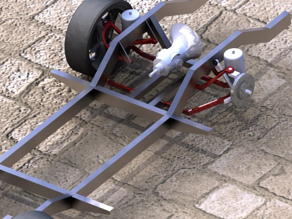
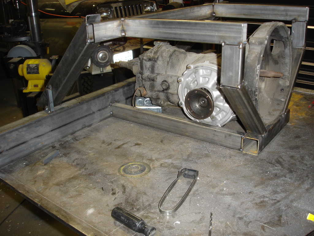
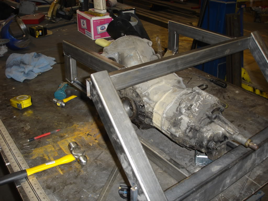
So in the drawing notice I have two tubes in parrallel to the transmission. That will be what the lower arm attaches to, much like the front. Also the top arms will mount very similiar as well. The only difference is I may spread the distance between the a arm mounts.
Also the scrub radius is mostly related to rim offset right?
Oh and ideas are welcome. I know most the terms so if you give it a shot I might be able to understand.
#43
http://www.google.com/imgres?imgurl=...ed=0CBoQ9QEwBA
Worlds longest link
I am having some problems with the SHforum right now not loading. I will try to keep up whenever it decides to work.
is there any reason for the width of the upper frame in the rear? Does it have to span a part of the vehicle, components, etc? I would consider moving those in to a point where you can minimize the length of the mount for the control arm. You can always widen it up to go around the engine after that.
#44
Thread Starter
2nd mouse gets the cheese
SuperBike
Joined: Jan 2008
Posts: 1,697
From: Beaverton, OR

no the frame in that place can be changed. There is some need for the rails of the frame to support that part of the body, but that would be it.
I also have been having issues with the forum. Frustrating...
Its amazing how much math is involved in making suspensions.
I also have been having issues with the forum. Frustrating...
Its amazing how much math is involved in making suspensions.
#46
Thread Starter
2nd mouse gets the cheese
SuperBike
Joined: Jan 2008
Posts: 1,697
From: Beaverton, OR

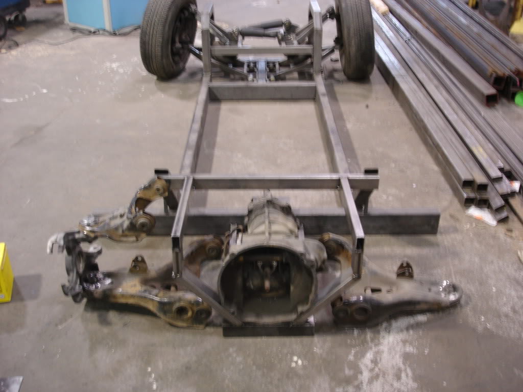
Back to the bus now that the cafe is more or less out of the way. Been trying to figure out how to make this work.
Autoteach, does the rear suspension need any caster? Or is zero degrees fine?
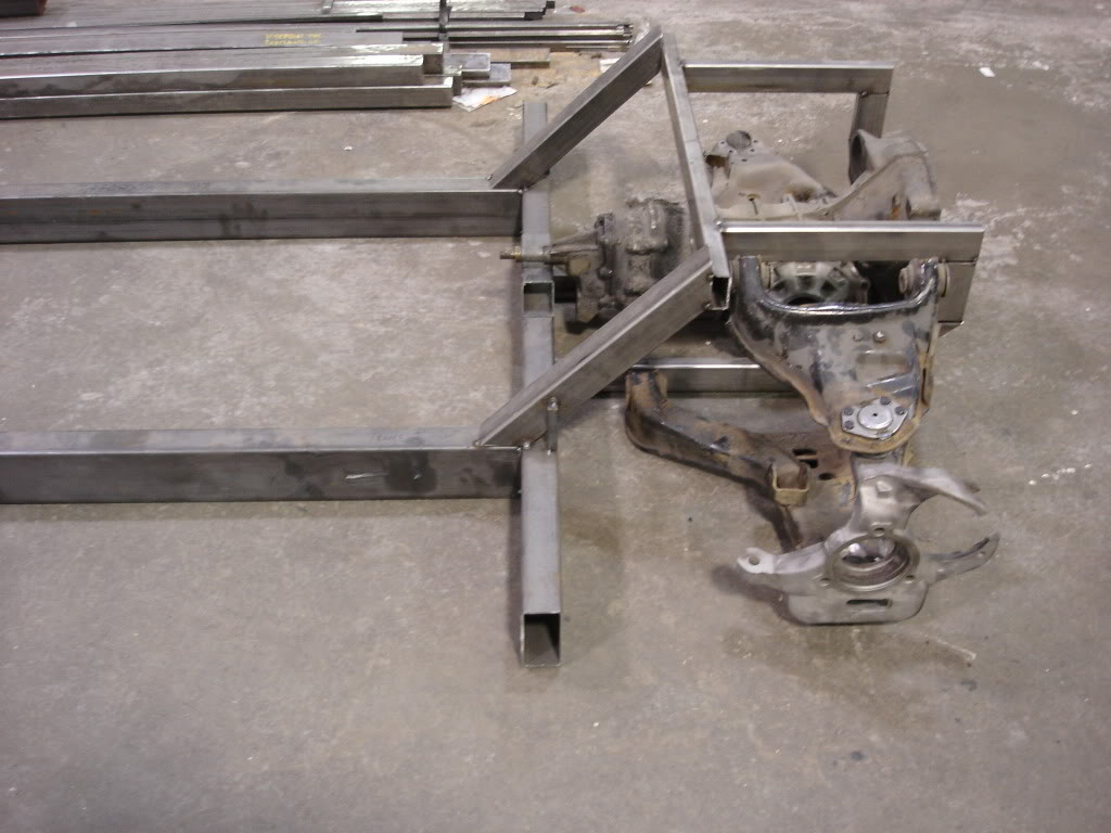
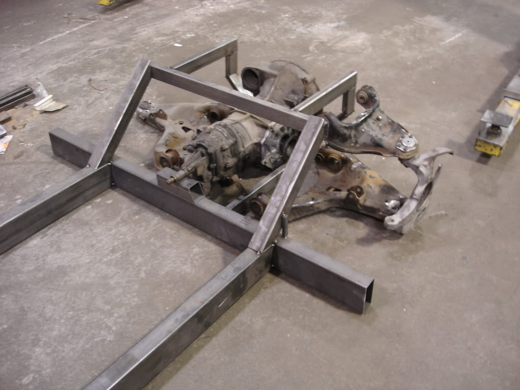
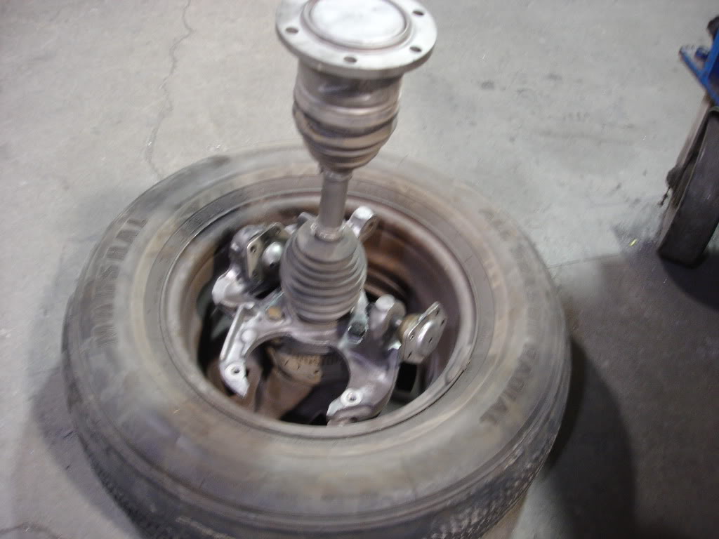
Autoteach, does the rear suspension need any caster? Or is zero degrees fine?


#47
http://www.modified.com/tech/0512_sc...t_4/index.html
I don't have the answer, but someone else might.
I don't have the answer, but someone else might.
#48
After looking around online they say that caster is only important on steering tires so from what it sounds like 0 is good for the rear as long as you aren't trying to make it a 4 wheel steer setup.
#49
Thread Starter
2nd mouse gets the cheese
SuperBike
Joined: Jan 2008
Posts: 1,697
From: Beaverton, OR

Thanks guys all you input is greatly appreciated. Thanks toys for an answer, I thought that was what I had read somewhere.
I don't know why but the last few days I have felt a little overwhelmed by the bus project, I haven't felt that way before about it. Oh well I will continue ahead and see if that helps.
I don't know why but the last few days I have felt a little overwhelmed by the bus project, I haven't felt that way before about it. Oh well I will continue ahead and see if that helps.
#50
Caster is only applicable to steerable wheels. It's the steering axis angle (line drawn through lower and upper ball joints, or lower ball joint and upper strut mount) compared to true vertical when viewed from the side. So you could go with whatever when you set it up, as long as it still allows you to adjust camber.
I taught computerized 4 wheel alignment in a vocational Brake and Suspension class for 25 years. That's one thing I miss since retiring, alignment was fun to teach.
I taught computerized 4 wheel alignment in a vocational Brake and Suspension class for 25 years. That's one thing I miss since retiring, alignment was fun to teach.
#51
well its a pretty awesome project and sometimes the overwhelming feelings happen I know how it works I currently have a few truck projects that get that way from time to time. Best thing to do is just keep cracking away at it and things seem to get better. Good luck with this.
Oh and by the way this project is making me want to build a VW bus as my next project.
Oh and by the way this project is making me want to build a VW bus as my next project.
#52
I hear you. Just focus on one thing at a time. With the way your Cafe came out, you'll do great on this.
#53
Thread Starter
2nd mouse gets the cheese
SuperBike
Joined: Jan 2008
Posts: 1,697
From: Beaverton, OR

well it funny because I know to keep everything in small project babysteps kinda deal, but I made the mistake of considering whether or not I may fail. It all started from being concerned my bushings are too loose. I don't know why the fail thoughts crept in because the fix is simple at best. Thanks for the encouragement.
Also I put some leather seats in my bus now it actually has a passenger seat, and a matching driver seat! They will have to be moved again because of the future tubs.
Also I put some leather seats in my bus now it actually has a passenger seat, and a matching driver seat! They will have to be moved again because of the future tubs.
#55
sweet bro. i love the bus my buddy boosted his and it sits on coilovers. its the most fun to take to the east coast for surf trips. it runs good too 8.2 in the 1/8th not bad for an old van. good luck and the fab looks good. do u make those cad pics.
#56
Thread Starter
2nd mouse gets the cheese
SuperBike
Joined: Jan 2008
Posts: 1,697
From: Beaverton, OR

Yeah, I do the 3d design stuff too. I went to back to college a year or so ago for drafting and 3d design. It helps with my actual paid job too. Although on the design stuff I get lazy and only design it to see if it works. If I had the program at home on my "bored" time I would have fun building it 100% correct.
#58
Thread Starter
2nd mouse gets the cheese
SuperBike
Joined: Jan 2008
Posts: 1,697
From: Beaverton, OR

So I have a few questions about my steering arms.
First off the tie rods are different lengths so will that affect things negatively? Will it produce bump steer?
Second I posted a few pictures do the angles look right in order to not have bump steer?

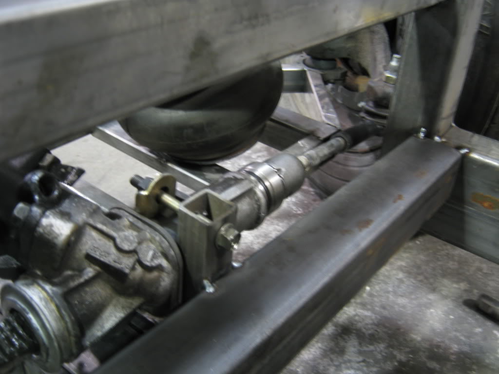

First off the tie rods are different lengths so will that affect things negatively? Will it produce bump steer?
Second I posted a few pictures do the angles look right in order to not have bump steer?


#59
It is going to produce some bump steer, and irregular at that. I don't have a solution for you, as every steering system has bump steer under some circumstances (i.e. wheels not straight). So, good luck, and be willing to dig back in to make changes.
#60
Thread Starter
2nd mouse gets the cheese
SuperBike
Joined: Jan 2008
Posts: 1,697
From: Beaverton, OR

Thanks auto, I expected some change but I am thinking it may be too much. At frame position it has alot of toe in. I may have to make it ride lower or rarely drop it to the frame, like for shows and things. The uncertainty of it working is what is driving me nuts. Anyways hopefully in a week or two the back will be finished mocked up and I can begin making all the adapter for the axles to the motor. Run all the pumbing and the brakes weld most of the frame up then start to consider the body transfer more seriously. If I am successful though epic... I shouldn't fear the failure I should chalk it up to training as the stuff I am learning to do this project has been intense.


